Using a webcam connected to a telescope is probably the least expensive expensive approach to astrophotography. The Xbox 360 LiveVision camera has been reported to be suitable for this purpose in a few astronomy forums. At the time of writing, it is still available for purchase, though it is not produced any more. Therefore it becomes harder to find for a decent price. I bought a new one for 11 EUR in an online store.
In order to exploit the full potential of the webcam with a telescope, some modifications are necessary. WARNING: These modifications will make the webcam useless for normal daytime use. And you will open the housing, which will void the guarantee. There are excellent step-by-step instructions available in the “Astro-Beano”-Blog, which proofed to be very helpful. Nevertheless, I will provide a similar walk-through here to document my approach.
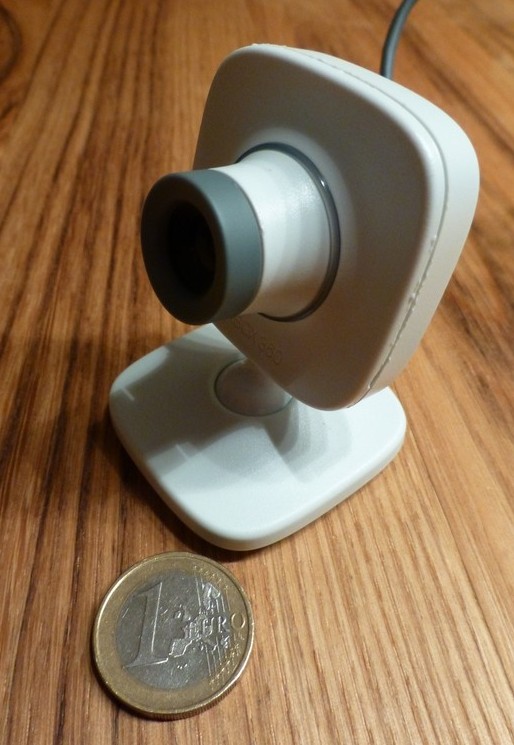
When I first saw the webcam, I was surprised how small it actually is. The picture below shows the front view of the camera together with a 1 EUR coin (approximately the same size as a US quarter dollar). The small dimensions are a big advantage. It is not bulky when connected to the focuser and does not add a lot of extra weight. So it can also be used with small telescopes on less stable mounts. The following steps are necessary for the modification of the webcam:
- Open the webcam housing by removing the front cover
- Removal of a plastic notch in the front cover
- Removal of four green light-emitting diodes (LEDs)
- Unscrew the of the lens socket (this step exposes the CCD chip of the camera!)
- Removal of the infra-red (IR) glass filter from the lens socket
- Reassembly of the camera
Since this procedure will expose the CCD chip of the camera, it should be done in an dust- and dirt-free environment. My dining table has proven to be sufficiently clean. You should allow for 60-90 minutes time. You will need the following tools:
- screwdriver with a wide flat head
- medium-size screwdriver for recessed head screws
- a sharp knife
- pincers are recommended
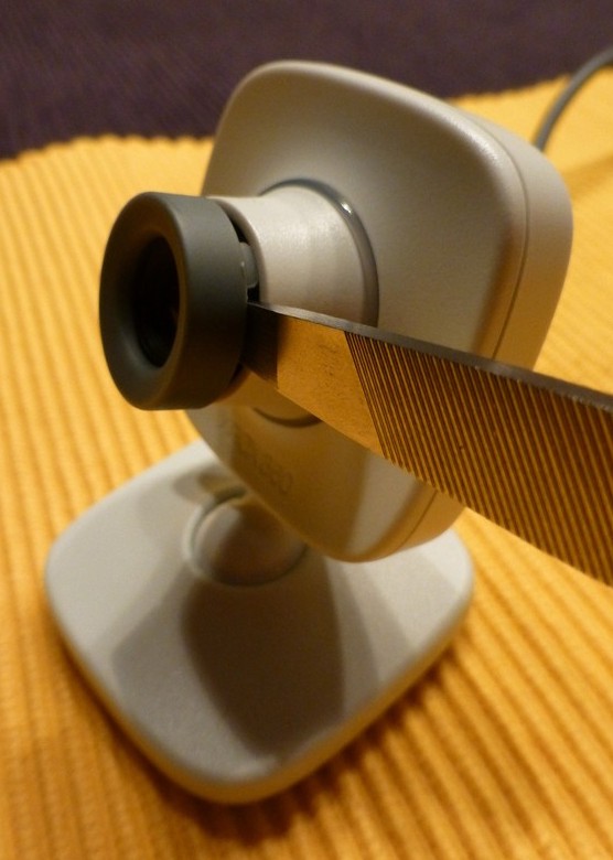
In addition to the webcam you will also need an adapter to connect it to your focuser. The best choice in my opinion is to buy a professionally turned part, which fits to the diameter of your focuser (typically 1.25″). These parts are available online in different astro-shops and cost between ~20-30 EUR. The picture on the right shows the webcam with the adapter in place, which is screwed into the lens socket. Before you start, I recommend that you read through the entire instructions to make sure that you know exactly what is coming towards you.
Step 1 – Remove the front cover
I have done so by gently pushing a flat hat screwdriver (actually it was the tip of a rasp from a multi-tool) between the gray lens ring and the lens tube and then twisting it carefully until the ring pops off. It should come of very easily without any force needed.
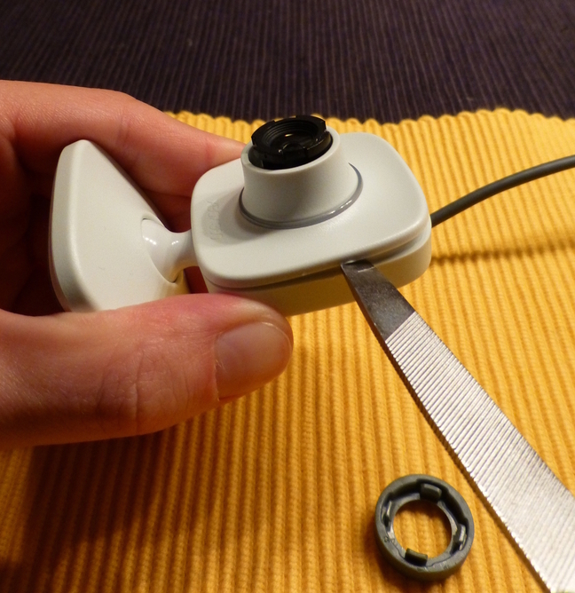
Next push the screwdriver between the front and the back of the housing and again gently turn it, which will make the catches pop open. Do so several times around the entire perimeter of the housing, also close to the base. You should them be able to lift off the front cover. Keep the lens in place and do not screw it out of its socket (yet) as it protects the CCD chip during the rest of the procedure.
Step 2 – Remove Plastic Notch
Focusing with this webcam is done manually by turning the gray lens ring until a clear image is obtained. To prevent that the lens is accidentally screwed out completely from the lens socket, the lens tube of the front cover has a plastic notch on the left side, which secures the lens. It is visible on the picture on the right. With the plastic notch removed, it is possible to swap between the telescope adapter and the original lens, which protects the CCD from dust, when not in use. I used a sharp knife to scratch away the plastic.
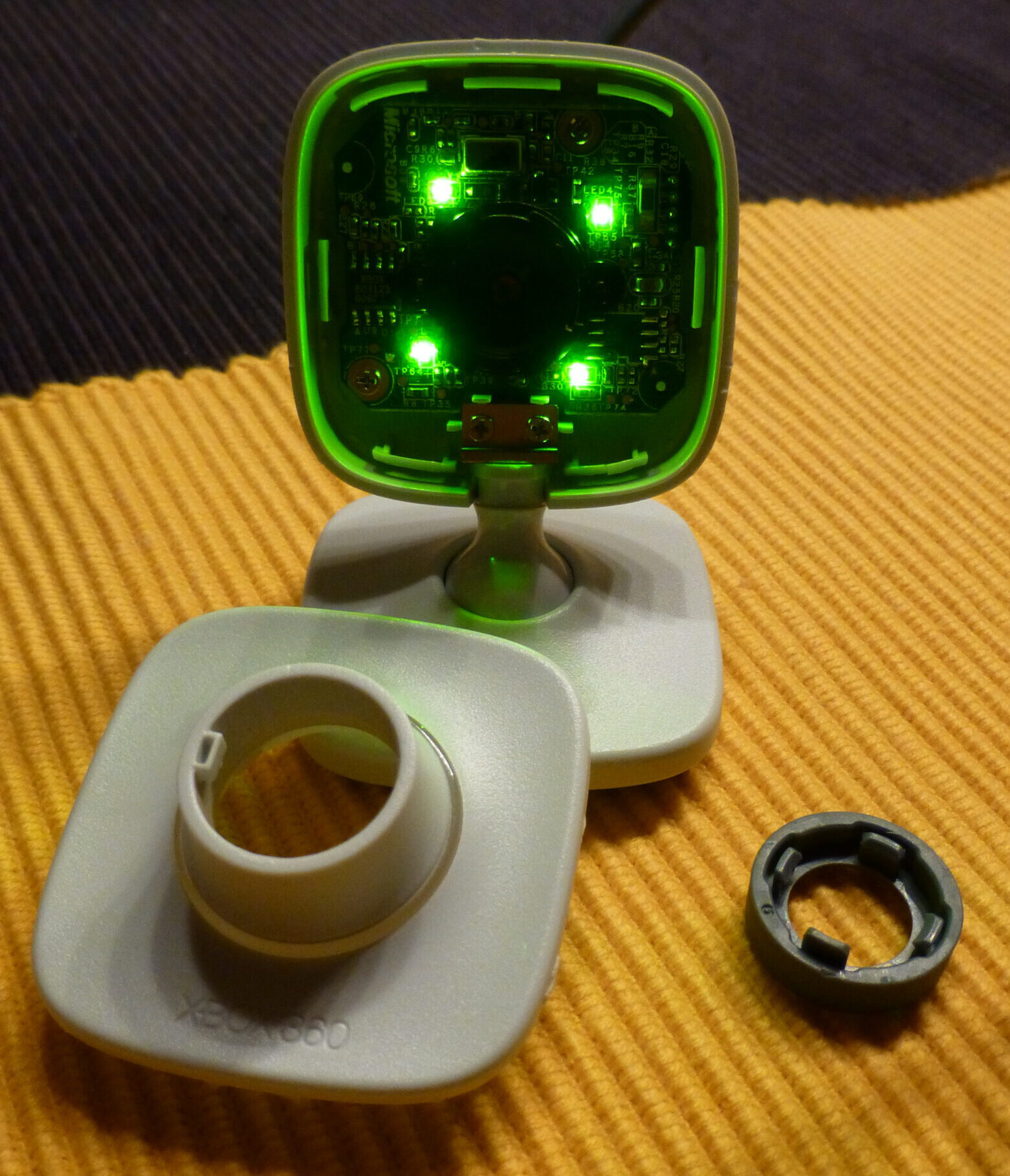
Step 3 – Remove the LEDs
This step is probably the most demanding of the entire process. The previous picture shows four green LEDs. They light up when the camera is active and takes videos. Though it looks fancy, it is quite a nuisance for astrophotography, where the light of these LEDs could potentially reach the CCD as stray light and ruin the picture. It is therefore recommended to remove them. The LEDs are very tiny (SMD), which makes it a bit challenging. However, if you do not want to bother or take a risk, you can also leave them on for now. I have taken picture of the moon and could not identify any adverse effects due to the LEDs, but I have not yet tested it with less bright objects.
There are several options to remove the LEDs: I have asked a friend, who is very good at SMD soldering and could remove them within a minute using proper equipment. An alternative option is to simply push the LEDs off the circuit board with a small screwdriver (good pincers may work as well). This method has been reported to work in the Astro-Beano-Blog. I have read elsewhere, that LEDs are also often painted over with black paint or a felt pen until no light is emitted any more.
Step 4 – Unscrew the circuit board and the lens socket
In this step, the CCD will be exposed for a short period of time to remove the infra-red (IR) glass filter from the lens socket. It is highly recommended to do so, since this will greatly increase the cameras sensitivity in low-light conditions. The Astro-Beano-Blog has comprehensive head-to-head comparisons of a camera with and without the IR filter. First, remove the two screws on the front side of the circuit board. After that, the board can be detached from the housing, but is still connected with the USB cable.
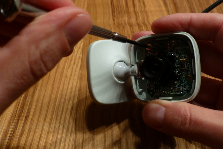
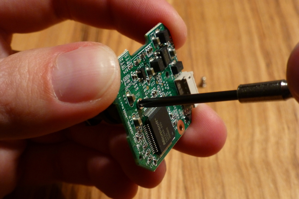
Even though I have disconnected the board for the further process, I recommend not to and leave the connector in place! It turned out that the connector is quite fragile. One cable had a loose contact after I reattached the plug. It took me quite a while to fix this. Remove the two screws on the back of the circuit board and remove the lens socket with the lens. Put the circuit board with the unprotected CCD away in a save place. Screw the lens out of the lens socket.
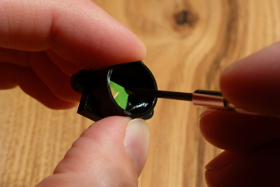
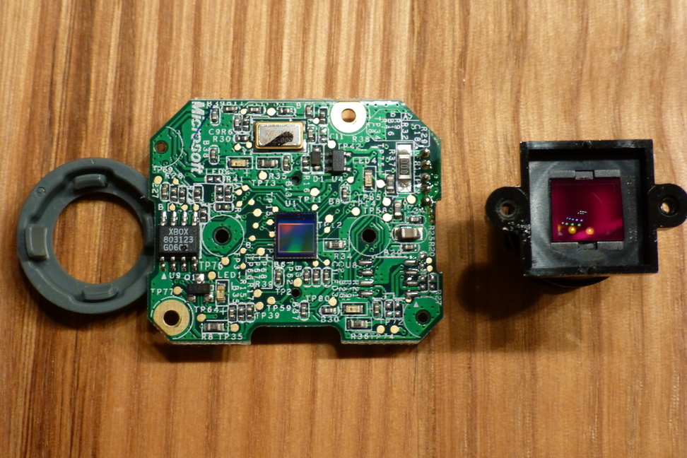
Step 5 – Remove the IR filter
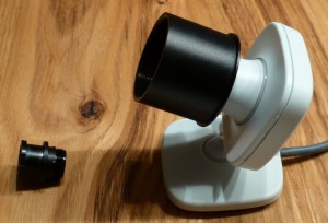
The picture on the right shows the front side of the camera’s circuit board with the CCD chip. The lens socket is on the right side next to it. The red plate is the IR filter, which we want to get rid of. To do this, push with a screwdriver through the front of the lens socket to one edge of the IR filter. This is shown in the picture below. The plate will come off the fitting without much effort. Apparently, it is glued into the fitting. Make sure to remove any remainders of the glue and any other dirt. Otherwise it might end up on the CCD chip.
Step 6 – Re-assembly of the camera
Put everything back together and make a test with the camera. Since the IR filter has been removed, the color balance of the camera does not work properly any more. Do not be surprised if you look awkward when taking a self-portrait. 😉
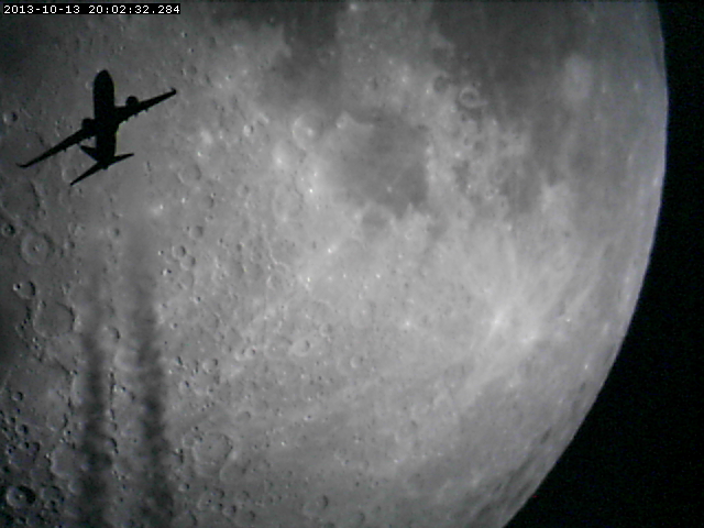
The picture below is a frame from a movie recorded with the Xbox 360 LiveVision Webcam. It was connected to my telescope (Newton 6″ f/5). Coincidentally, I have recorded an airplane (probably a Boeing 737) flying in front of the moon!