The Problem
All reviews agree: this is a noisy printer! The noise is generated by the original stepper motor drivers but mainly also by the four different fans of the printer. These are the hotend cooling fan and the part cooling fan, both located in the hotend cover. Then there are also two more fans in the printer’s base for cooling the power supply unit and the mainboard with the drivers.
I have decided to start with the fans in the hotend and replace them with quieter ones. This also involves printing a replacement of the hotend cover with modified air inlets on the side. The original cover has a couple of holes on each side which obstruct the air flow and probably also creates noise. It would be better if the entire air intake section of the fans was cut out.
IMPORTANT: If you also intend to do this mod, please read this all the way through before you start. The update did not go quite as I expected and I would do it differently next time!
There is no shortage on websites and tutorial videos about replacing the fans and the cover. I found this video very well done and helpful to get an insight into what awaits you when you remove the covers. Chris actually does not replace the frontend cover but just swaps out the hotend cooling fan…had I only listened to him.
Here is another tutorial about the hotend fan replacement: https://the3dprinterbee.com/anycubic-mega-s-fan-upgrade/#Hot-End_Fan.
I wanted to go one step further and also replace the part cooling fan as well as the cover as suggested in this blog (in german): https://sypke.de/anycubic-i3-mega-und-sinnvolle-upgrades/. It turned out that I ran into some issues with that and ended up not installing the front part of the cover. But more on this later.
The Solution
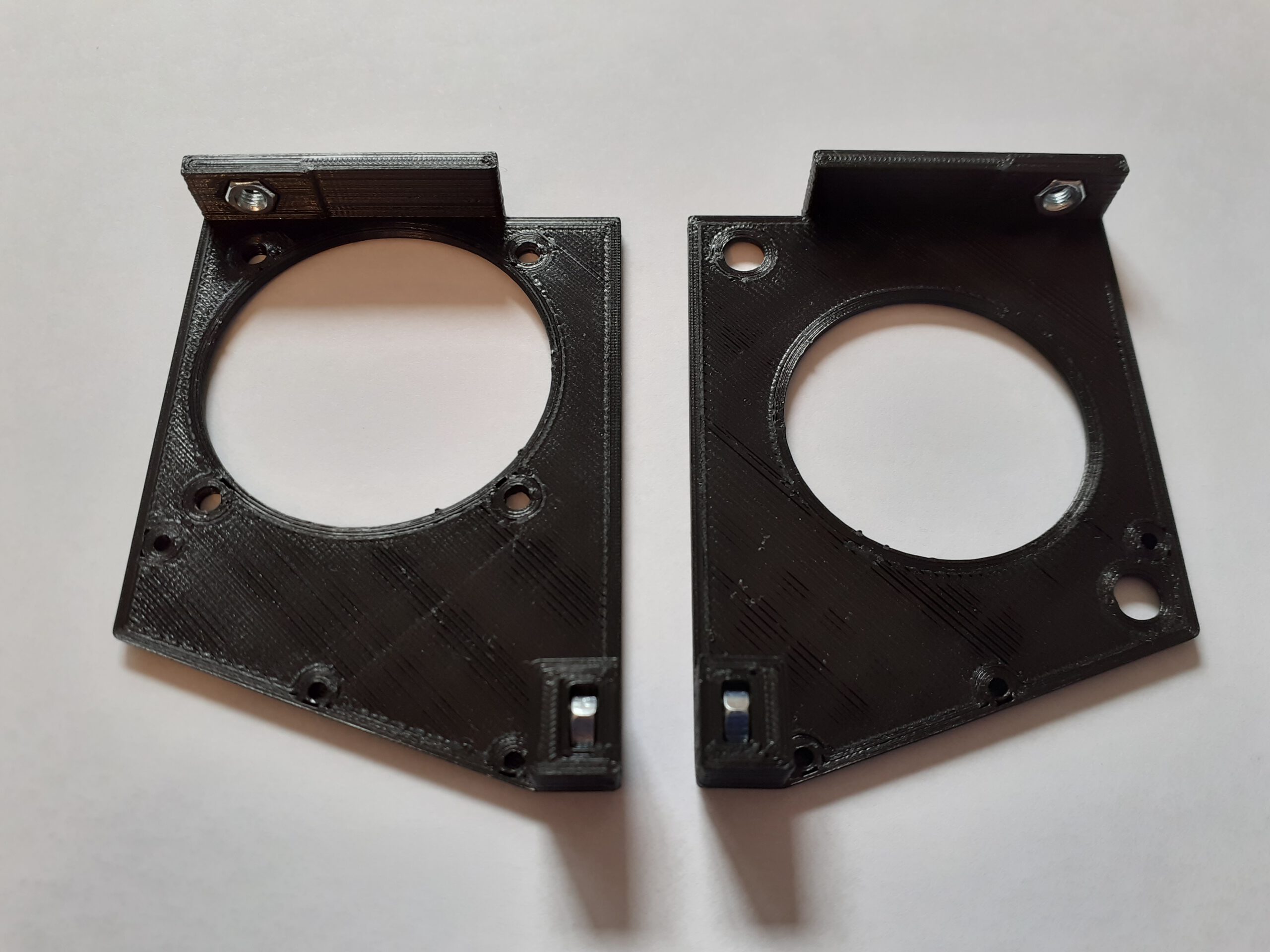
There is a design for a hotend cover replacement that seemed to fit all my needs: https://www.thingiverse.com/thing:2706092. It has the air intakes completely cut out and also has a modification of the mounting holes on the left panel that fits my replacement fan cooling fan. I printed all four parts, but in the end it turned out that I did not mount the front grille (top right on the picture).
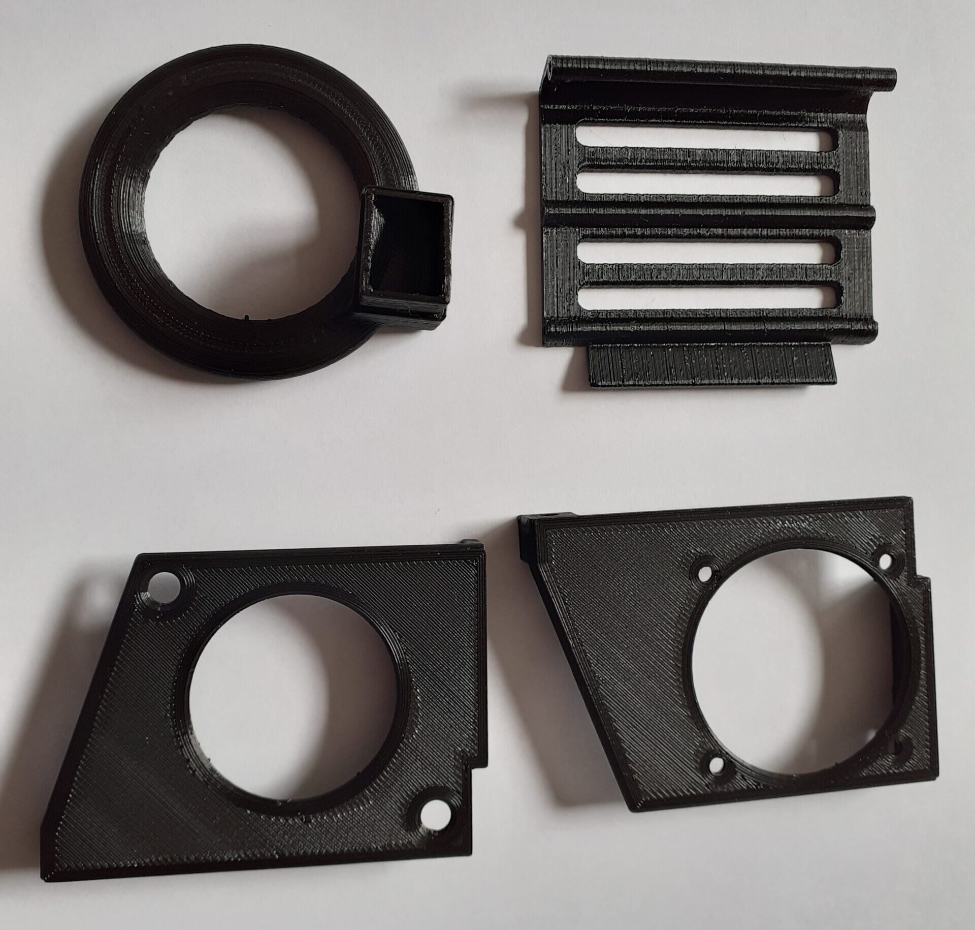
Note that this cover will not fit the original part cooling fan because the placements of the mounting holes on the left side panel is different. This part in shown on the bottom left on the picture. I believe that this design https://www.thingiverse.com/thing:3414693 could be a good alternative, but I have not yet tested it.
The Material
I have used the following components for this modification:
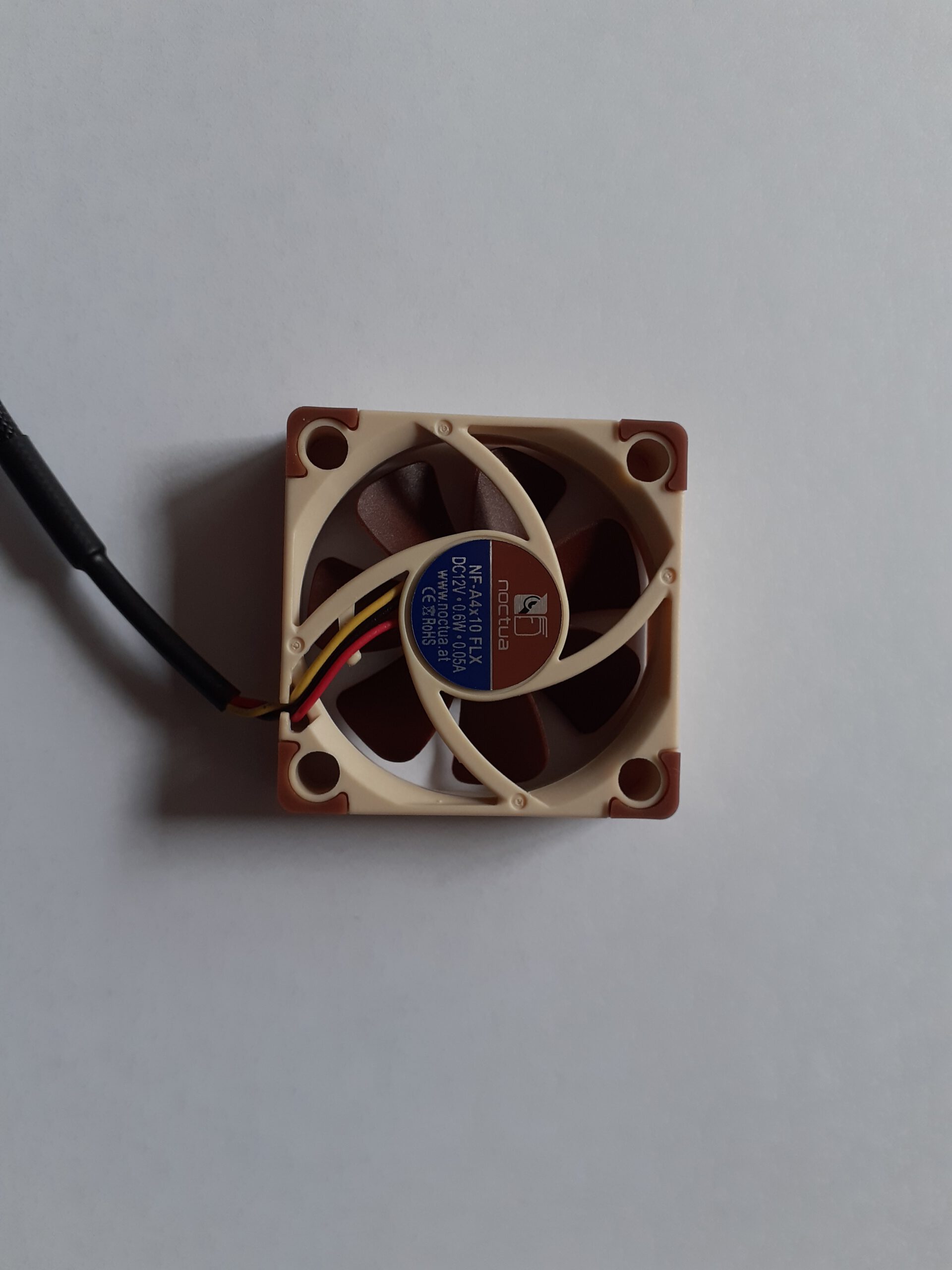
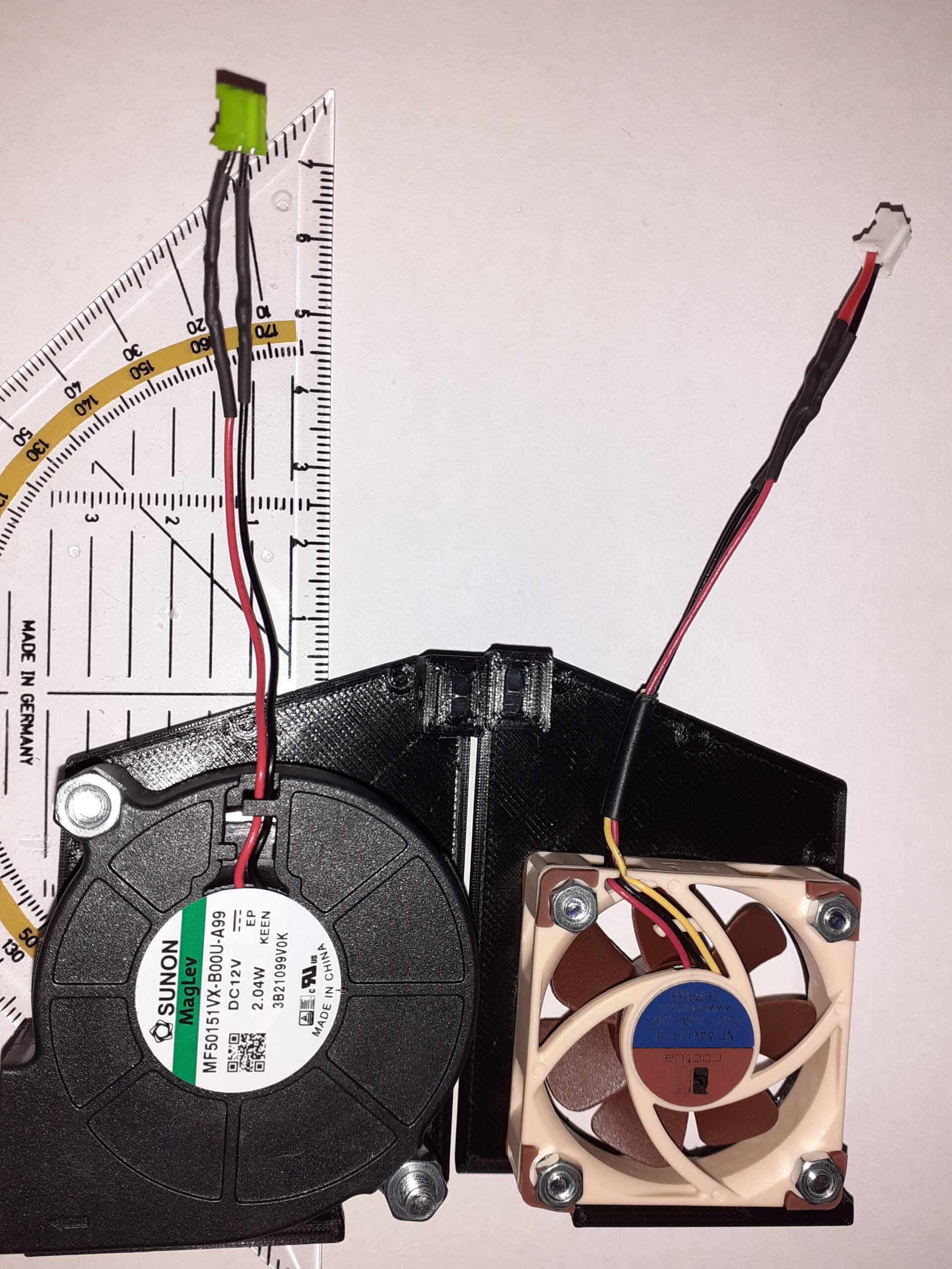
- Noctua NF-A4x10 FLX 12V for the hotend fan
- 4x M3x16 screws with nuts to mount the hotend fan
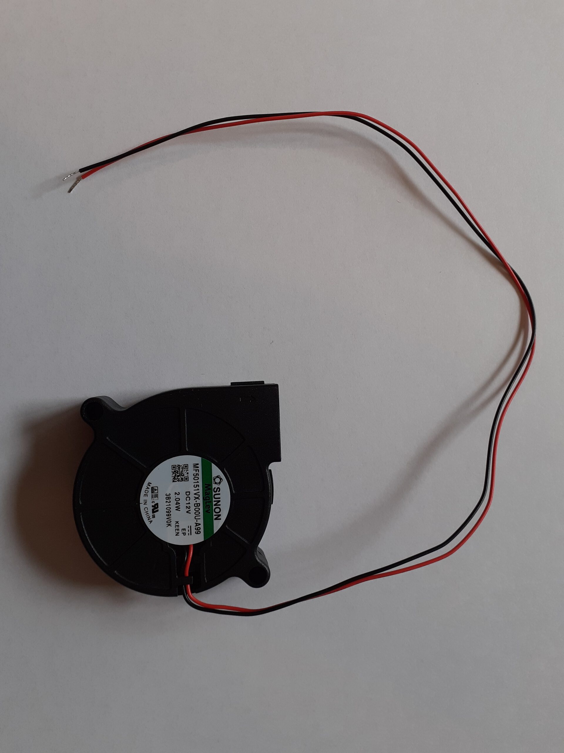
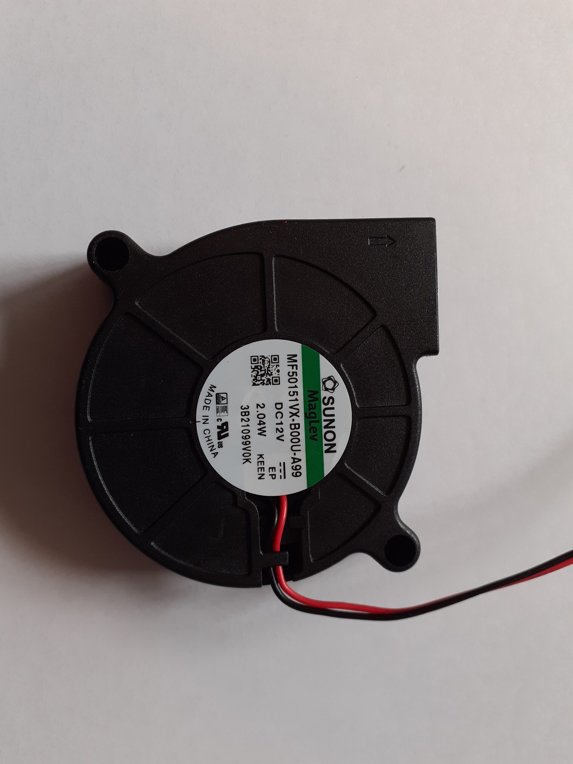
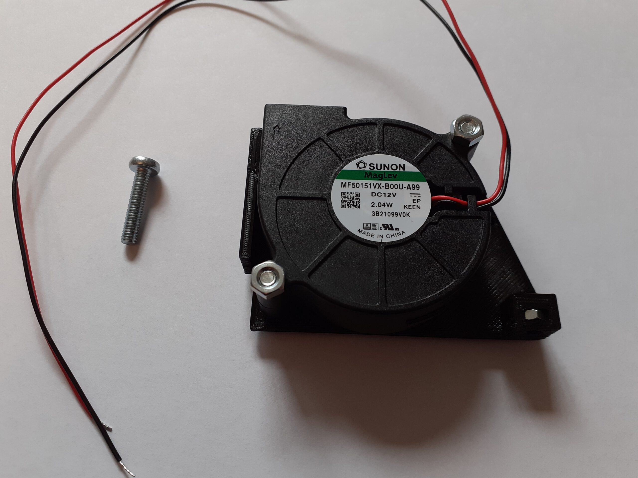
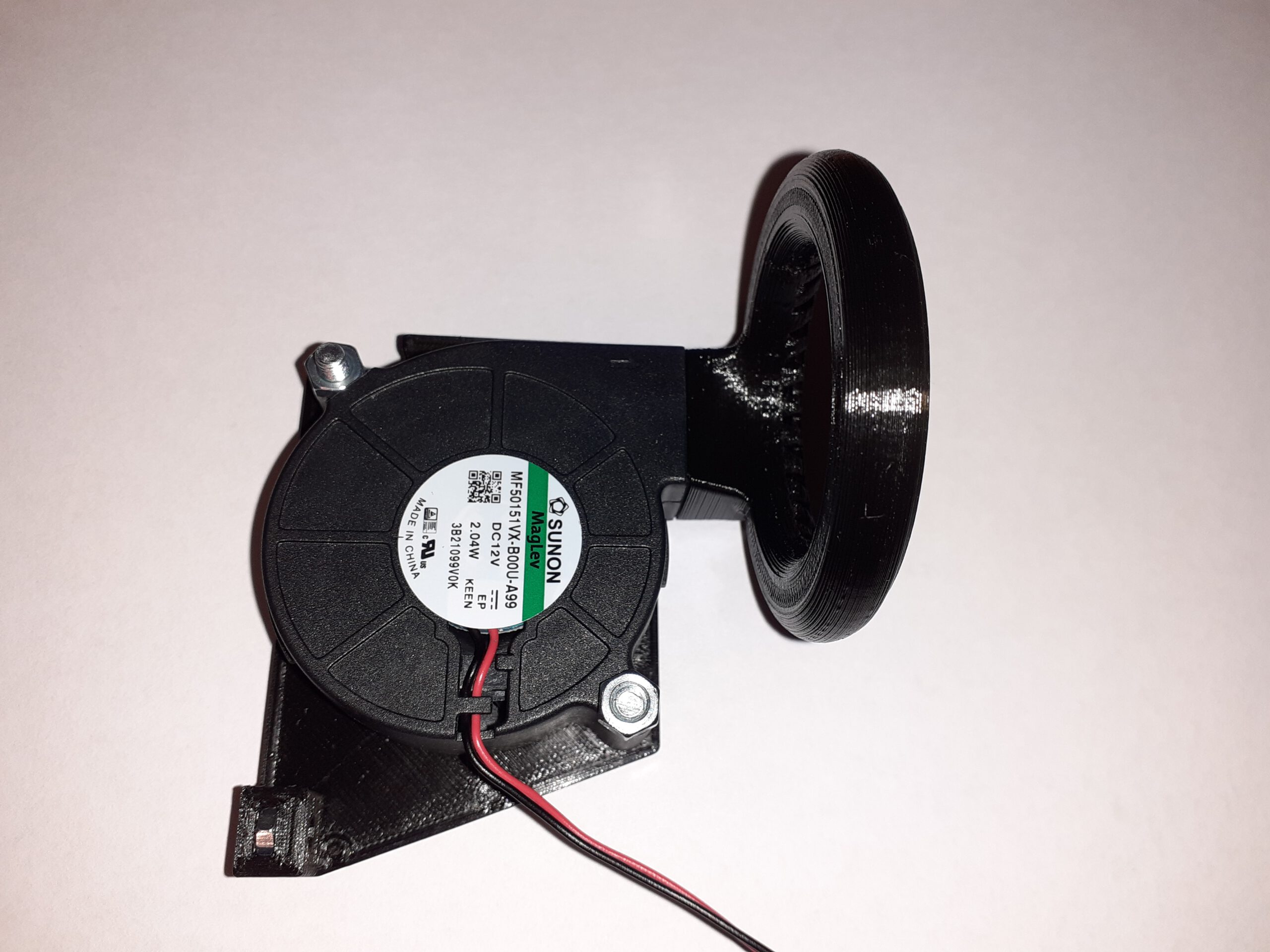
- Sunon 5015 12V radial fan for the part cooling fan
- 2x M4x20 screws with nuts to mount the part cooling fan
- 2x M3x10 screws with nuts to mount the hotend cover (top side)
- 2x M3x5 screws with nuts to mount the hotend cover (back side)
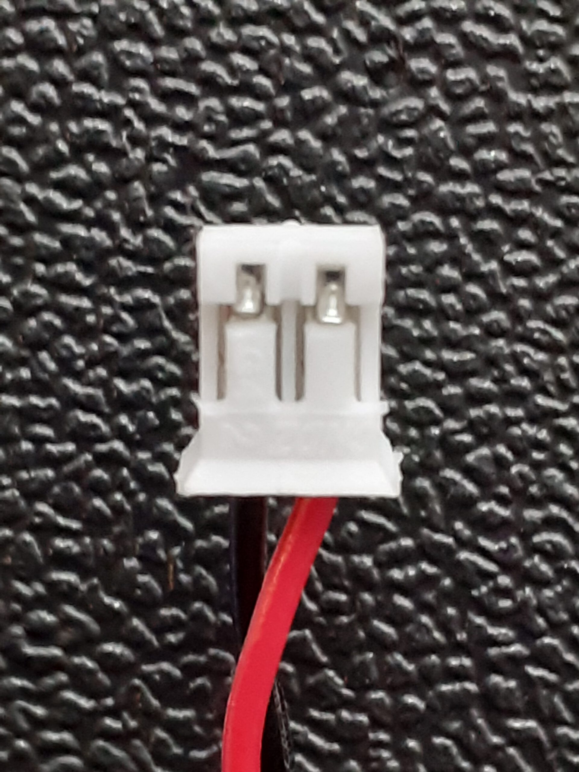
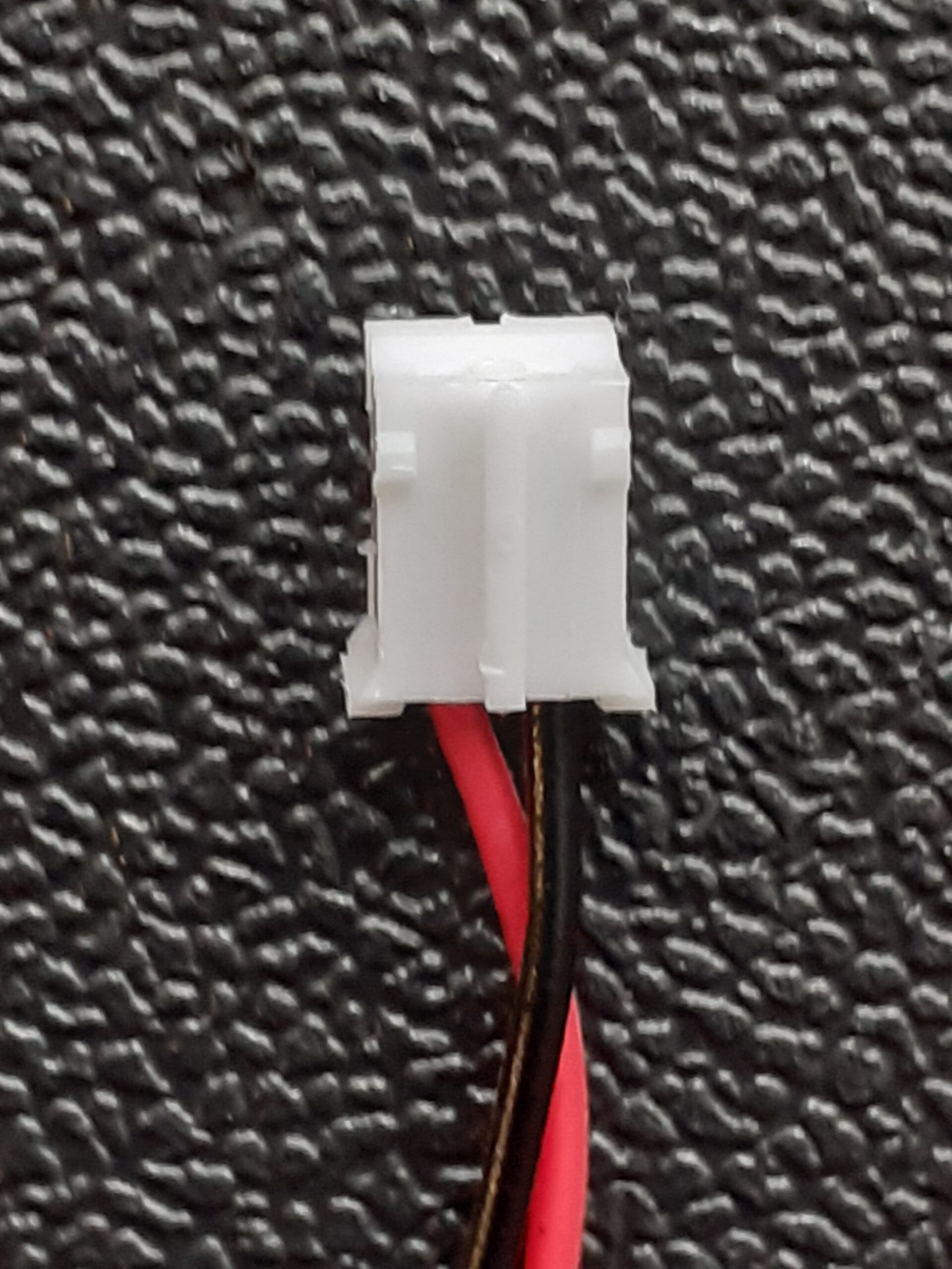
- Optional: 2 connectors for the new fans
If you do not want to cut off and re-use the connectors from the original fans, then you need the connector shown below. I had one of these laying around, so I used it for the new part cooling fan and did not touch the original one. This allows me to revert back to the old fan if I want to. I recommend you to do the same if possible.
You will also need some tools:
- A soldering iron for replacing the fan connectors
- Shrinking tube (recommended) or electrical tape for isolation of the soldered wires
- A set of Allen keys
- A pair of pliers
- A saw (Really? Oh yes! That indicates it did not go so smooth at one point.)
The Print
I choose to print the fan duct separately first, then the two side covers with the outside wall facing the print bed and finally the front grille. The front part was printed standing up with the thin side on the print bed. I enabled supports in CURA under the latch on the top of the grille. Even though this part was not needed on hindsight, it was an interesting test. The hotend cable routing mod came in handy for printing parts with larger z height. The original instructions say that the three parts for the cover must to be glued together. Fortunately I did not do this, as I had problems fitting all the cables in. But more on that later.
The Installation
First things first: switch the printer off and disconnect it from the power supply!
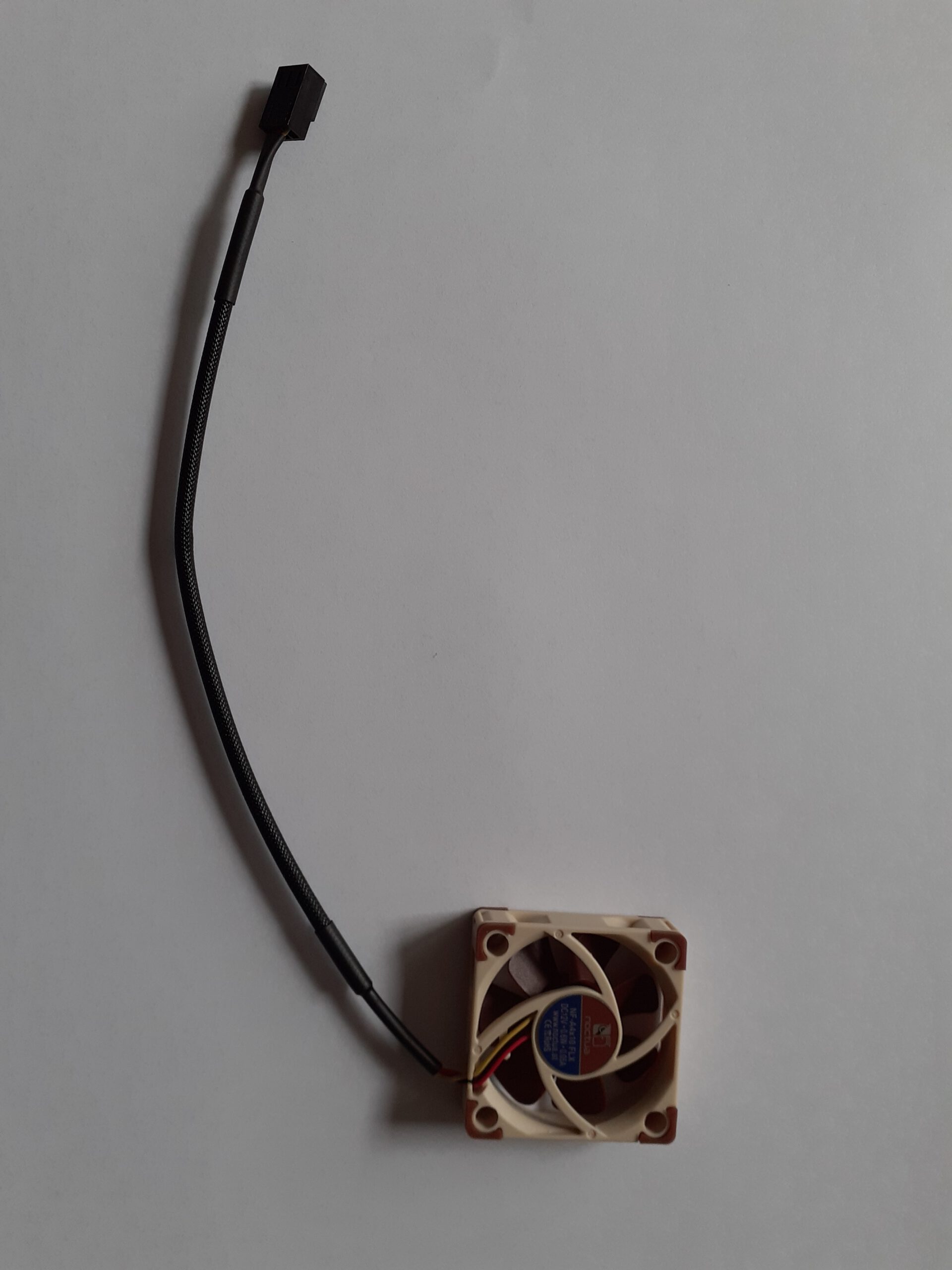
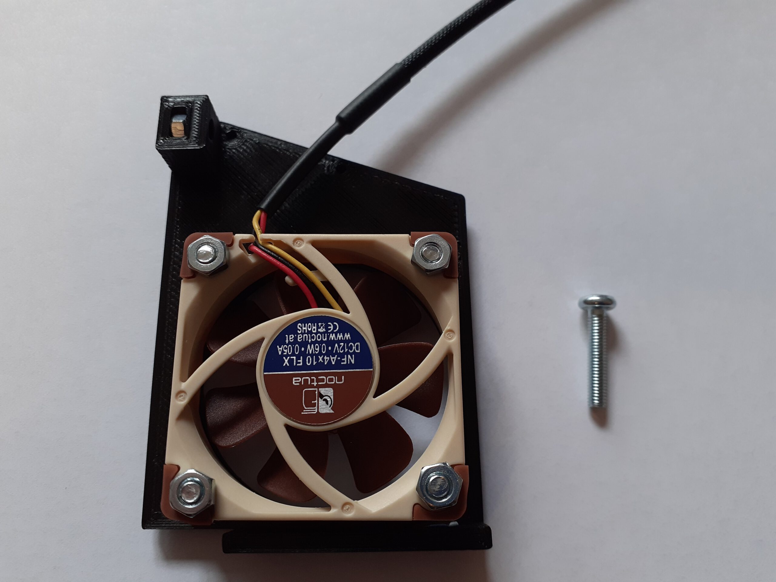
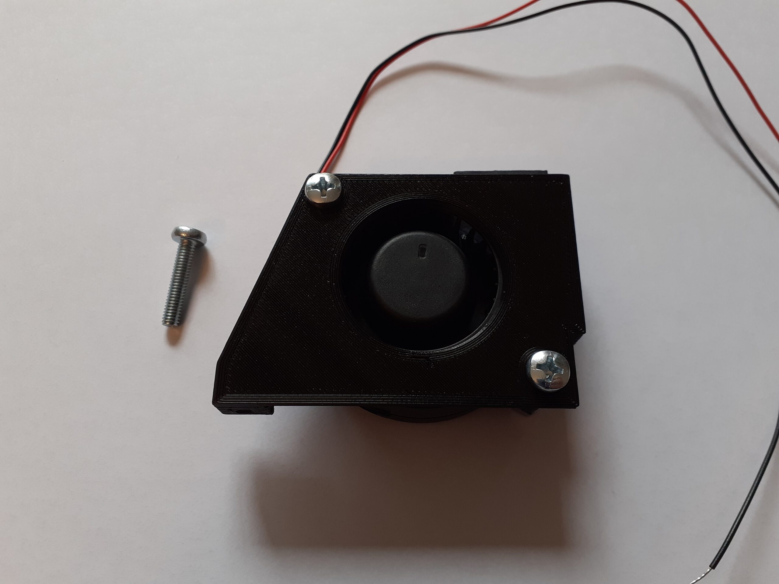
The picture below show the Noctura hotend fan and the Sunon part cooling fan prior to installation. The Notura has a three pin connector. The Sunon fan came without a connector. I decided to first mount them to the side panel and then take care of the connectors. Doing it the other way around could be easier.
Before anything else, push four M3 nuts into the slots at the top and at the back side of the left and right cover. It takes a lot of pressure to them in. That’s okay, it is supposed to be a tight fit.
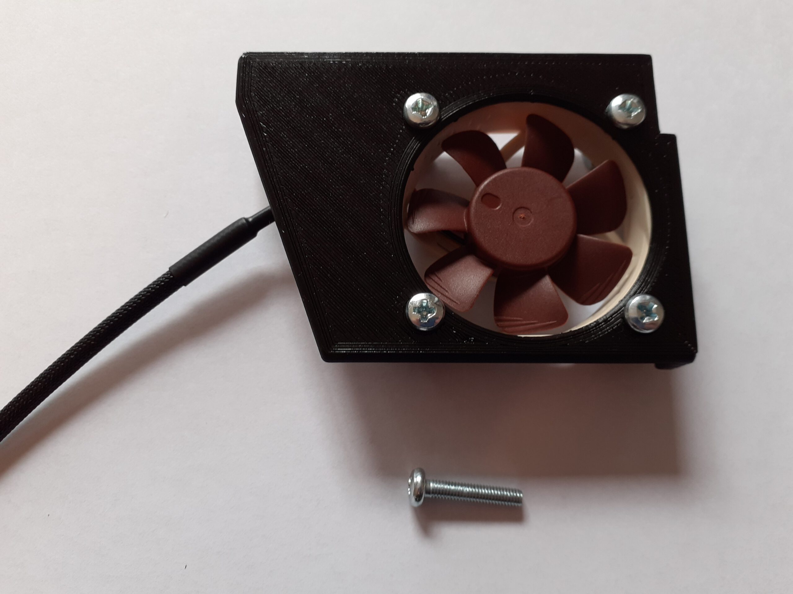
Then I have screwed fans to the left and right cover. I used four M3x16 screws and nuts for the Noctura hotend fan and two M4x20 screws and nuts for the Sunon part cooling fan. Note the orientation of the fans. The hotend fan is supposed to vent air into the housing.
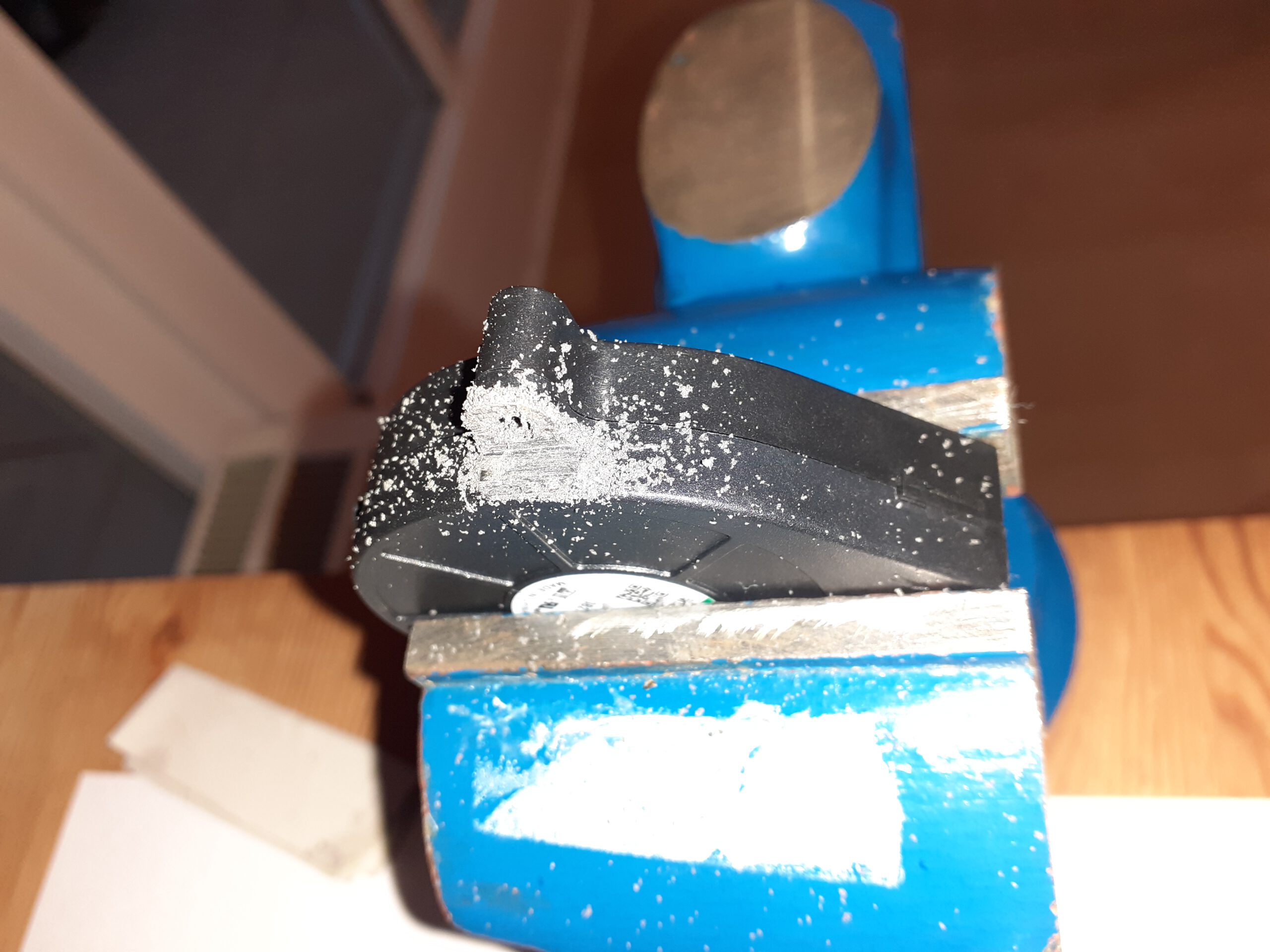
One of these nuts should soon become an issue. The author of the part used screws with a tapered head (the holes actually have a countersink for that) and NO NUTS to secure the fan! However, I did not have any screws that would fit and hold the fan in place. It turned out that the nut on the top would interfere with the mounting bracket of the hotend and the left panel would not close properly.
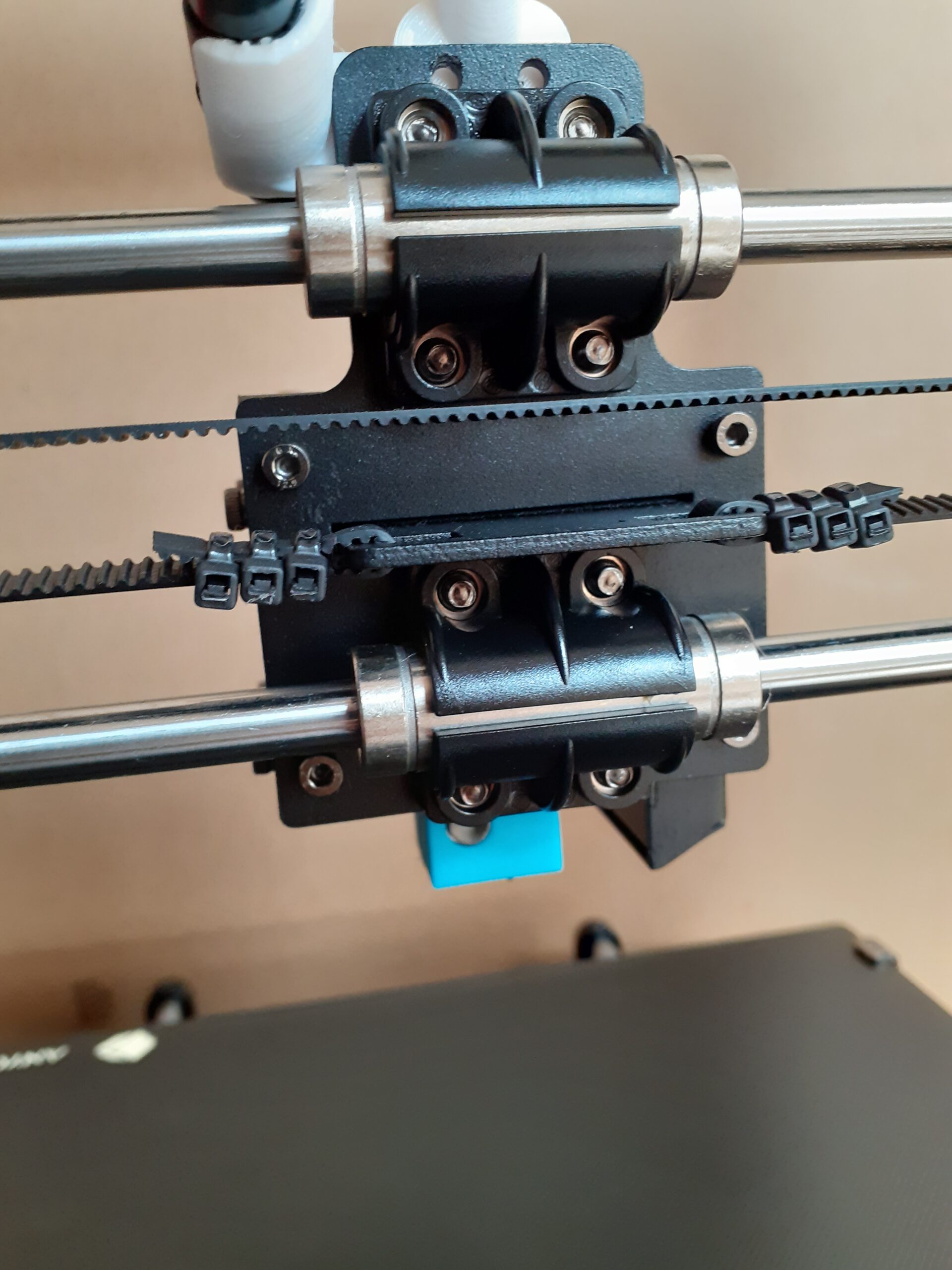
The bracket that fixed the hotend to the top of the cover is shown in the left picture. I ended up cutting out a part of the fan housing with a saw. I made it just deep enough to provided enough room for the M4 nut. Cutting the screw was not necessary, fortunately.
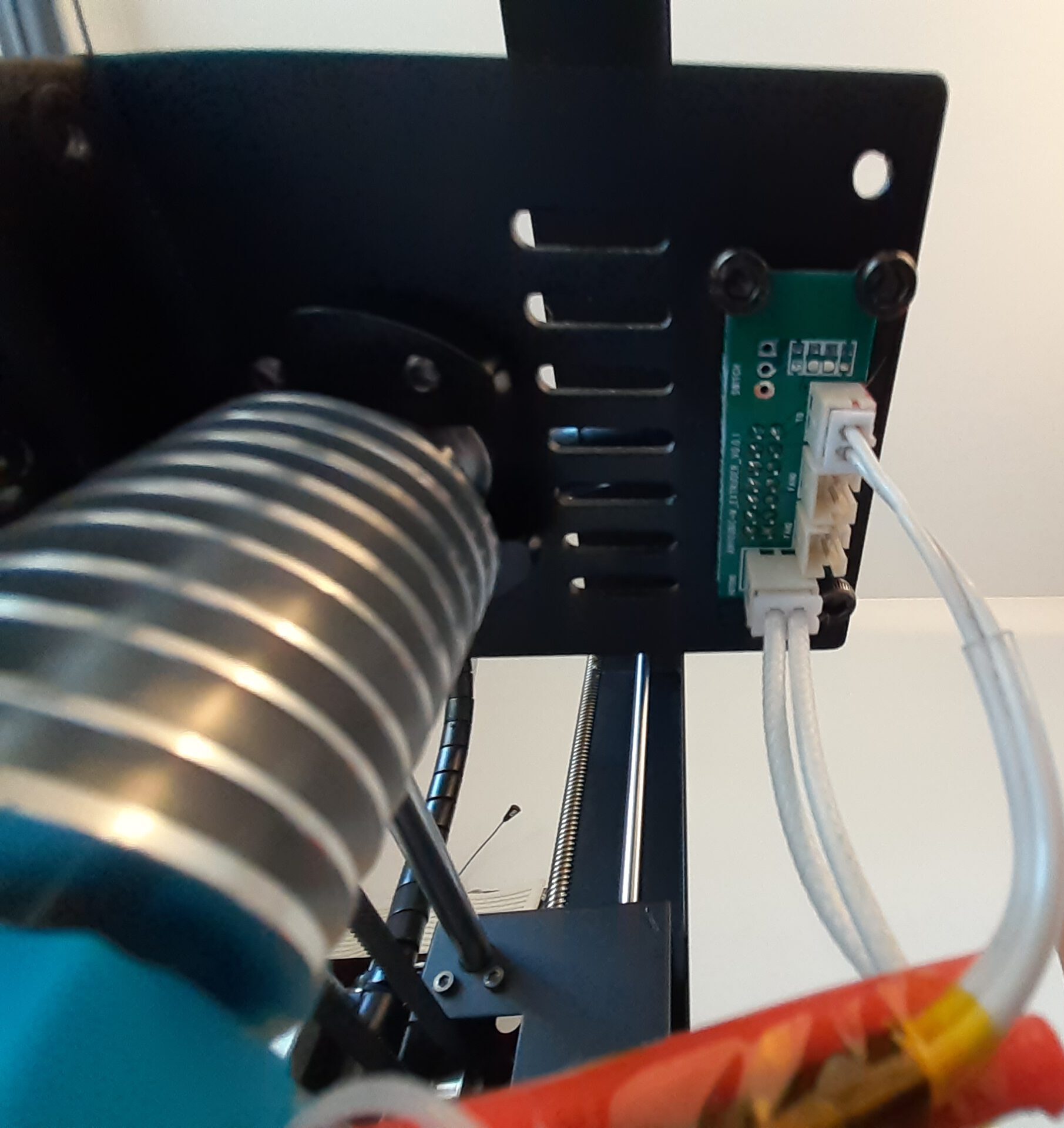
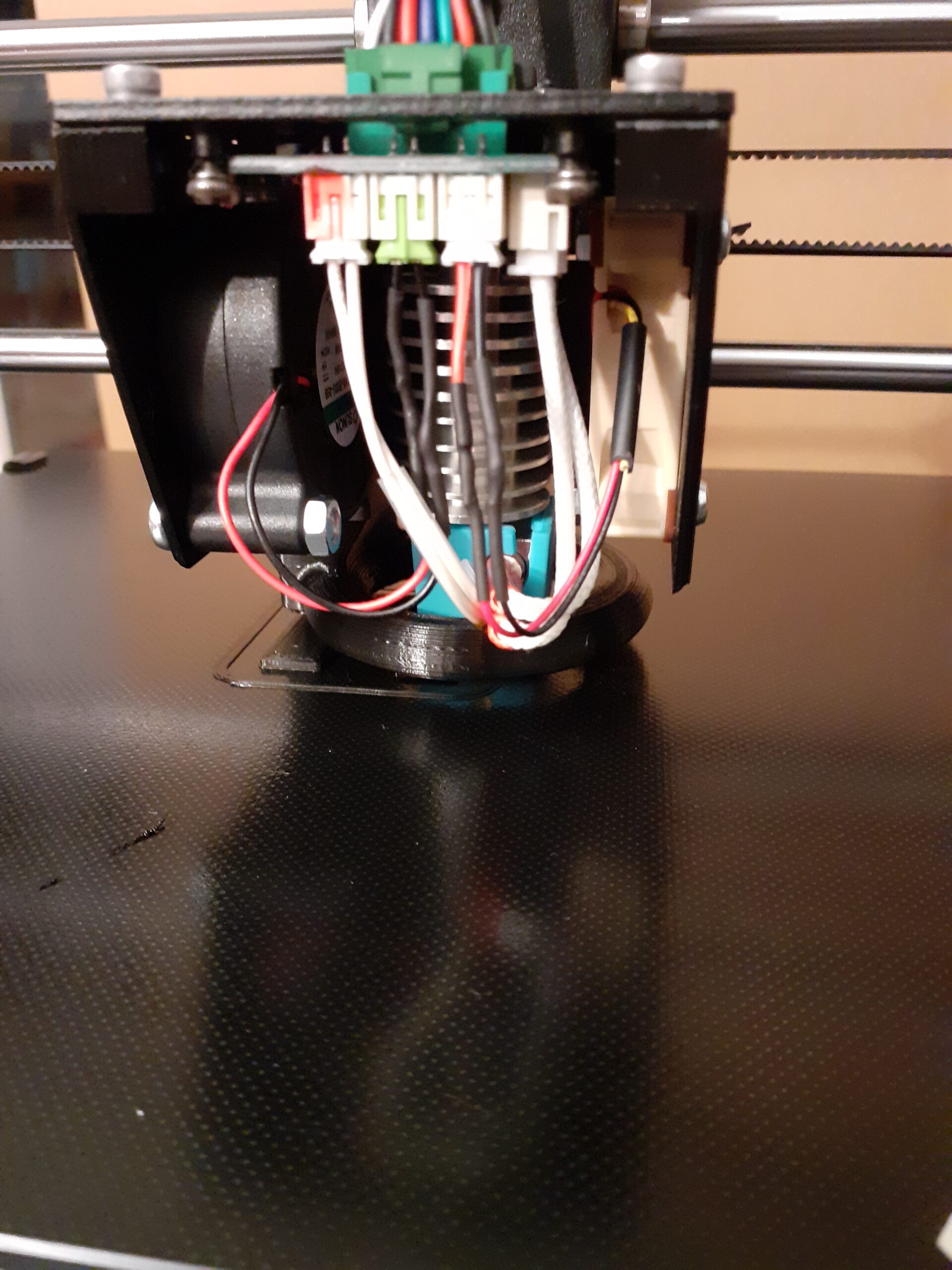
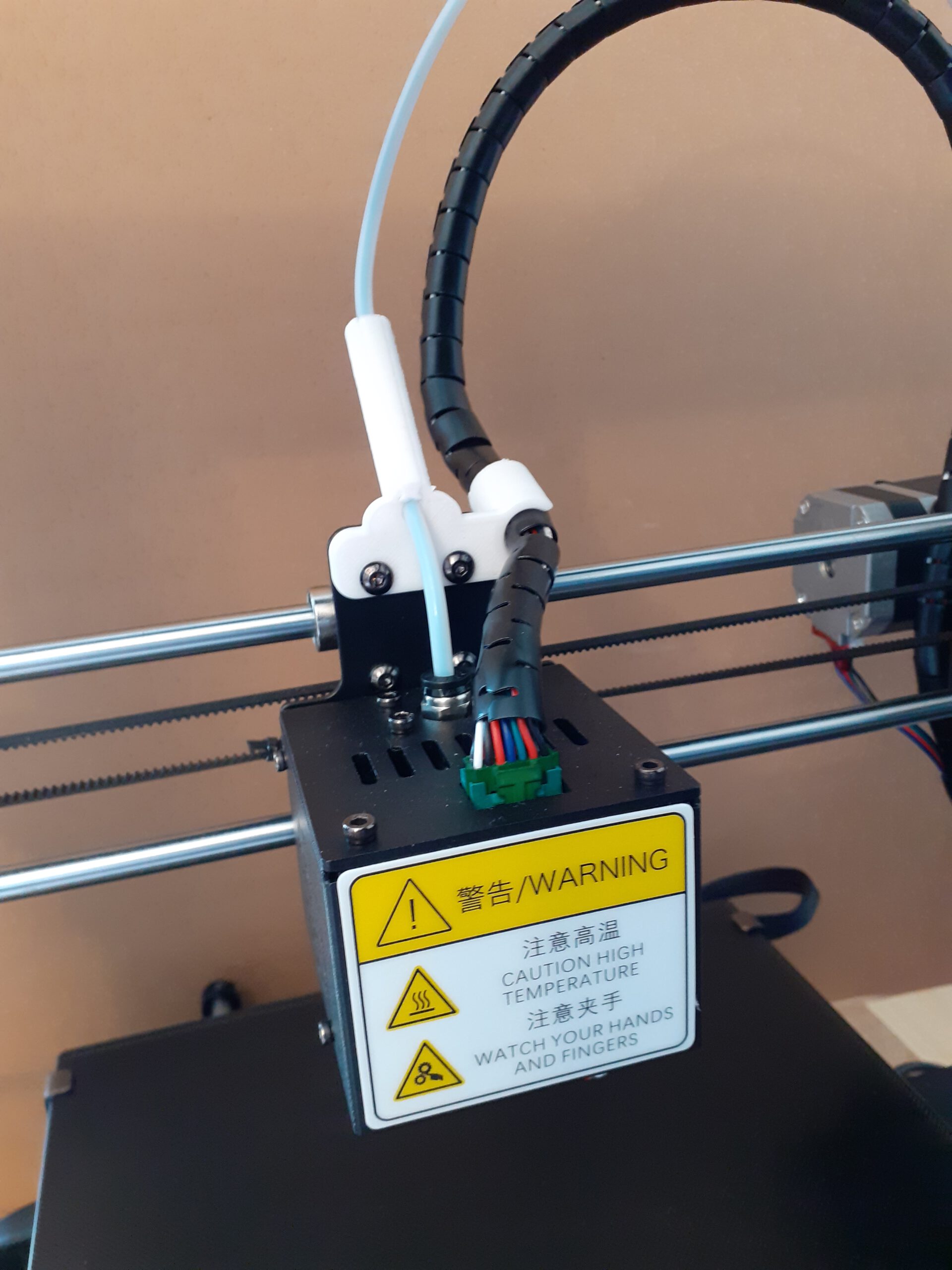
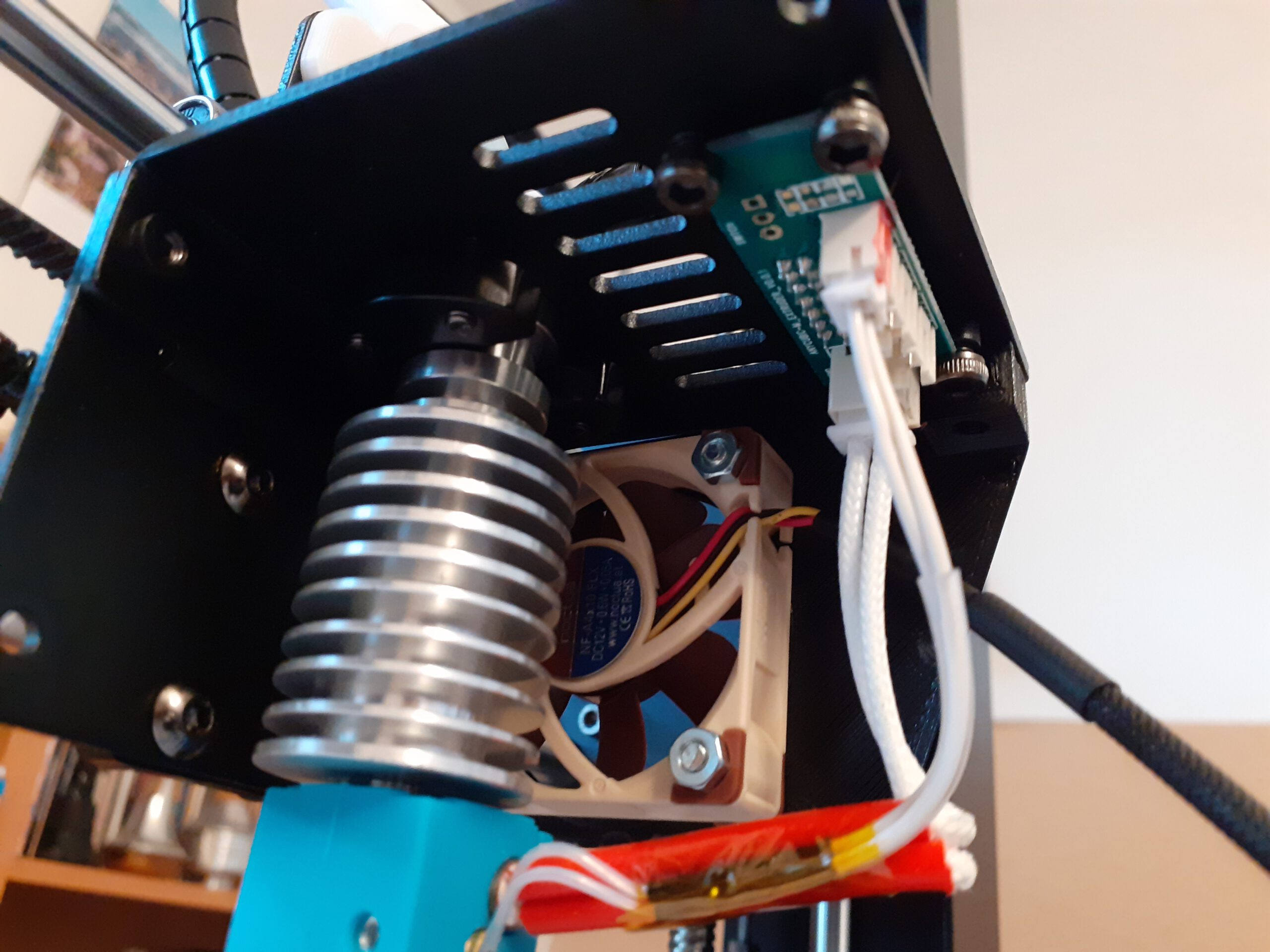
Okay, with that problem solved, on to the connectors. Time to setup the soldering iron and heat it up. In the meantime, the hotend cover can be removed. Remove the two front screws on top and the two bottom screws on the back. The two top screw on the back must stay in place. The cover than drops down. This is a good moment to take a photo of the wiring. The part cooling fan on the left is connected to the middle left pins and the hotend fan on right is connected to the middle right pins. That is easy to remember but better take that picture. The other cables are the hotend heater and the temperature sensor. Leave them in place.
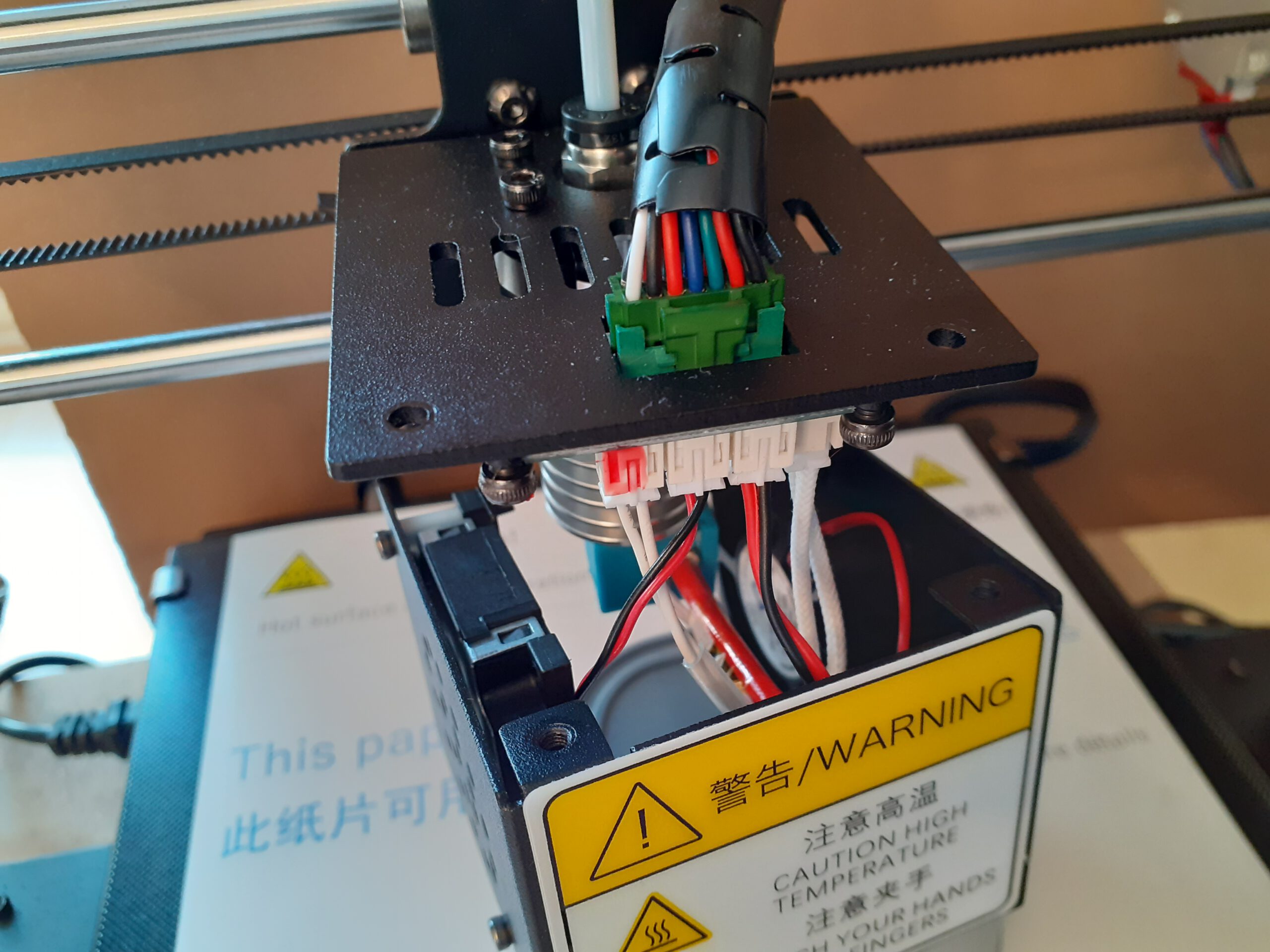
Now the fan connections can be removed. When I did this, the sockets came sliding out as well. Damn, which way had they been in before? Glad I had the picture so I was sure how to put them back in and did not reverse polarity on the fans.
Now it is time to adapt the connectors on the new fans. Because of the troubles I had with the part cooling fan, I decided to not leave the original fan intact and use the spare one I already had for the new fan. I only cut off the connector of the original hotend fan. The Noctura fan is a straight swap with this one, so I could have just put it in the old housing and would still be ready to print.
I cut the wires of the new fans and soldered the new connectors to them. The resulting cable length on both is about 7 centimeters. On the Nocture fan, the yellow cable is not used and must be cut back even further to get out of the way. Make sure to put the shrinking tube on the cable BEFORE starting to solder. Almost forgot this for the second fan. Why is this so hard to remember?
Next the side panels are screwed into place. I used the two M3x10 screws for the top and the original M3x5 screws for the back part. The fan duct must be pushed into the radial fan outlet. Connect the fans to the correct pins (remember left goes left, right goes right). And this is it, all done!
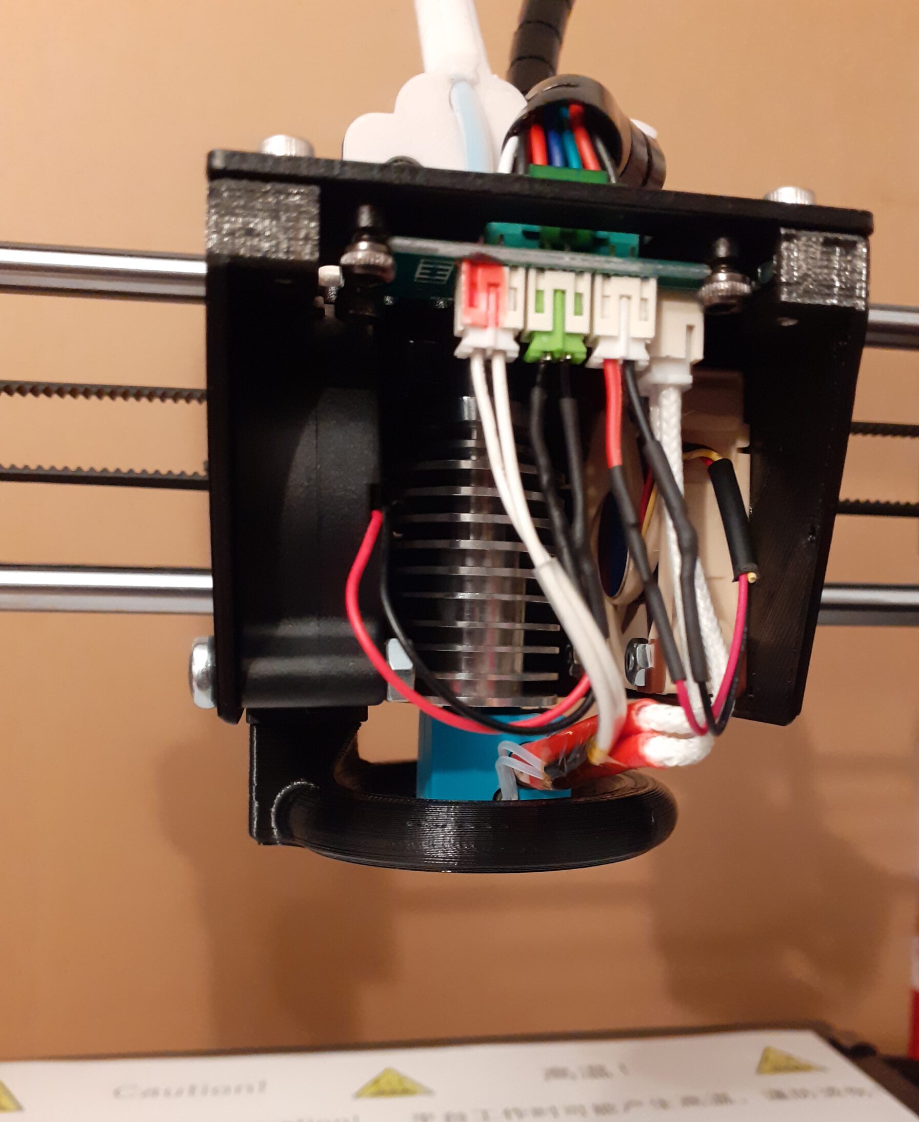
But wait, there is one part left. What about the fancy front grille? The problem is that the slanted geometry of this design leave very little room for the cables. As you can see in the bottom left pictures above, the hotend heating and sensor cable stick out quite far to the front. These cable to not bent very easily. In order to close the front, I would have to squeeze everything in there and that did not feel right. So, the front is open now. No loss in functionality, the printer still prints. But what about the esthetics? Well, let’s change topic!
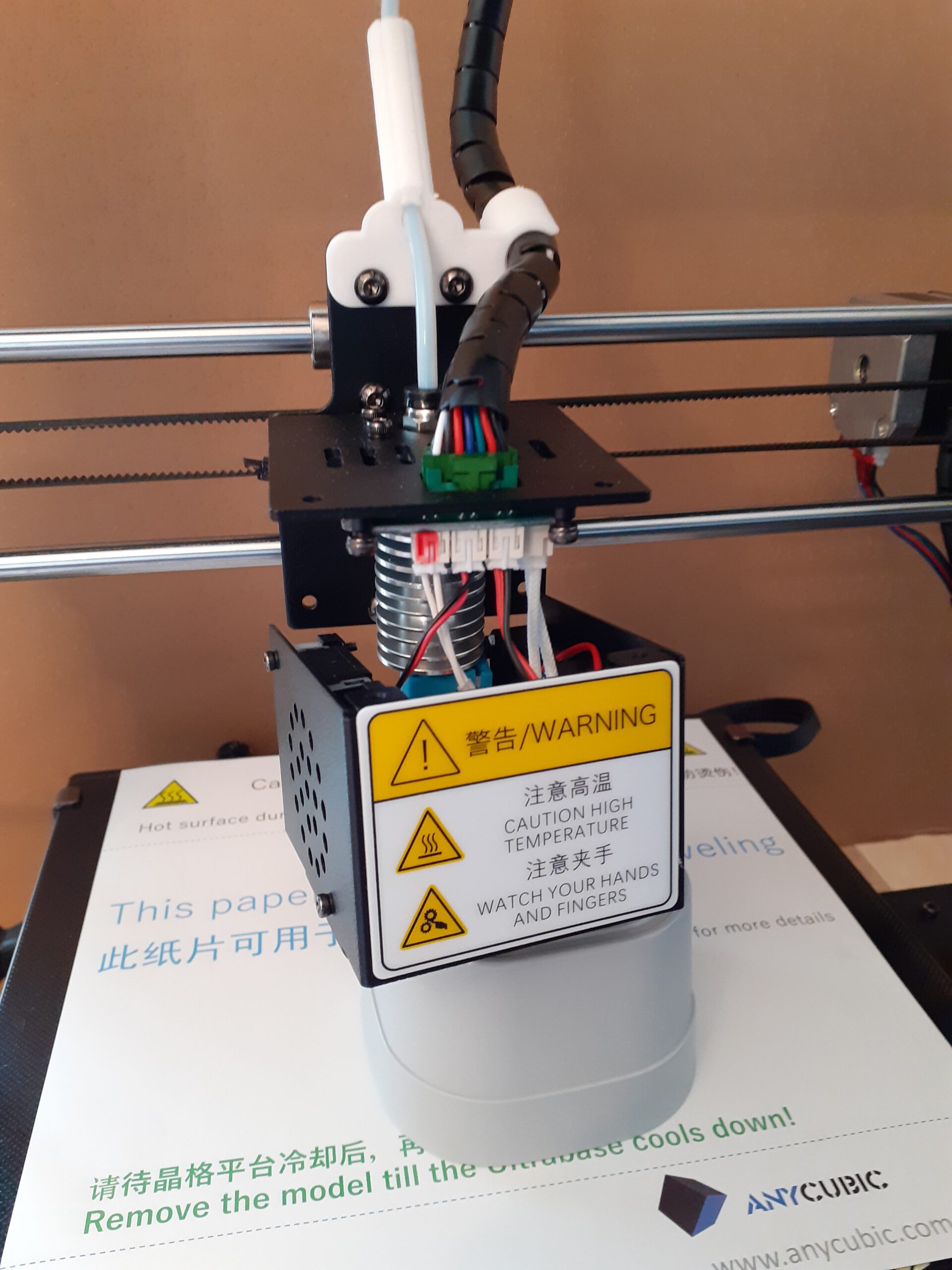
Testing is necessary before we go back into production. After the printer is switched on the fans do not turn. That is normal, because the hotend cooling fan only starts when the nozzles reaches about 60°C and the part cooling fan is only activated when the acutal print starts. So manually heat up the nozzle and verify that the fan turns. The Notura was expensive, but it is also very silent. I did not hear it at all. When that works, select a test print and check that the part cooling fan works as well.
The Resume
Was it worth it? That is difficult question for this mod. Replacing the hotend fan was definitely an improvement. The original one was terribly loud. Also, using a different design housing with completely cut out air intakes has probably helped as well. As a minimal approach I would probably just replace this fan and use a housing designed for the original part cooling fan but with no air intake obstructions like this one: https://www.thingiverse.com/thing:3414693.
Would I replace the part cooling fan again? Not sure. I have not compared the fan noise directly. I have read in some blogs that there is not that much to gain. The bigger problem is, that this slanted housing design is the only one I found that has the proper screw holes for this fan. I would prefer a housing design with a straight front and more room for the cables. Leaving the front open like I did does not harm the functionality, but it does not look good. I will have to design my own housing or redesign an existing one. So I have unfinished business here.
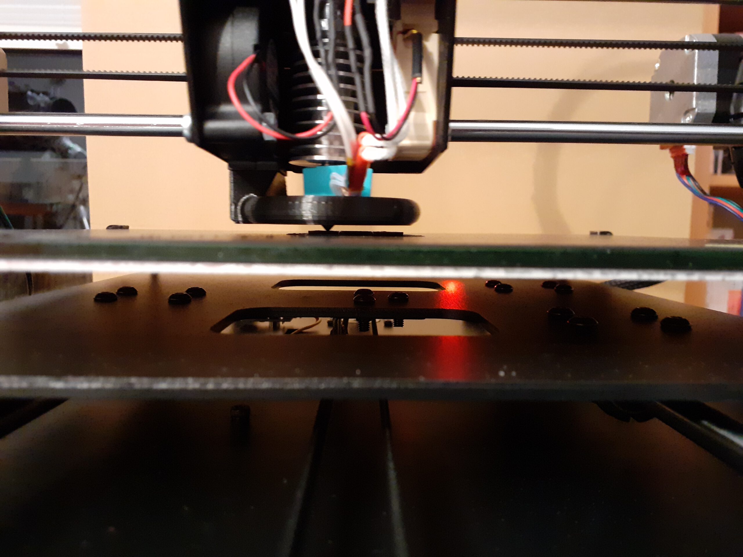
What about the circular fan duct? It is a great design, no question. The rational behind using it is that for the original part, the cold air reaches the fresh layer of filament only from one side. Now, the air comes from all sides, cooling the filament more evenly. I cannot yet asses how much the print quality improves. I can already see one side effect of this larger fan duct, and that is that the view of the print is blocked from all sides. The bottom of the duct is so low that the nozzle clears it only by a few millimeters. This makes visual control of the first layer much harder, especially for small prints.
Now that I have it, I will leave it on for a while, but I have already seen other designs that fit the Sunon 5015 fan. This set includes a semi-circular fan duct design: https://www.thingiverse.com/thing:2919245. There is another alternative, that directs air from the front and the back: https://www.thingiverse.com/thing:4011070. I am keeping those for future modifications, so stay tuned.